So this went well…
The Intel 4004 microprocessor has slightly weird power supply requirements by modern standards. You see, it needs to be supplied with +5V DC, and -10V DC at the same time to work.
(It turns out that this is an artifact of the MCS-4 chipset using PMOS technology not the more modern CMOS. Wikipedia has a good description of the constraints of PMOS, but these include the requirement for a number of supply voltages including a relatively negative voltage.)
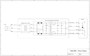
Now, I found this example circuit in someone else’s project:

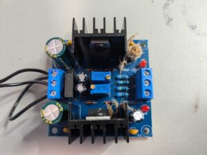
Which to me looked quite a lot like these kits from ebay being fed by an AC power supply:

So I ordered a kit off ebay, and then ratted around in the garage to find a random AC power supply. Luckily I found one, because they’re not super common compared to the DC power supplies I have huge mounds of. Now of course the kit had no assembly instructions apart from the markings on the PCB, which seemed mostly good enough when coupled with some random googling for polarity information. However, I really needed documentation about the input pins.
However, that kit appears to be this aliexpress listing, which has a nicer diagram:

So I ran with all of that, although its not really clear to me what is ground on an AC power supply, so I just put one output of the supply into the two outer connectors and the other one into the middle. I’m not sure that isn’t wrong somehow. Even then, it didn’t go completely as expected, given the small amount of exploding my kit did…

Did the kit ship with a bad capacitor? Am I a numpty somehow? The board did briefly produce two voltages, but when I went to adjust the potentiometers it got all explody.
Theory one: the pins on the heat sinks should be grounded. I initially didn’t solder these because I’ve had bad experiences trying to solder heat sinks before. However, these ones weren’t too bad.
Theory two: one of the electrolytic capacitors was installed backwards and I didn’t notice. While this is possible, I don’t really have any evidence either way, because I don’t have any pictures from before detonation to compare to.
Either way, I replaced the exploded capacitor and had another go. The power supply ran for five minutes without load with no explosions, so I then adjusted the potentiometers to the right target voltages. Still no exploding! So I guess the pins on the heat sinks really really matter?
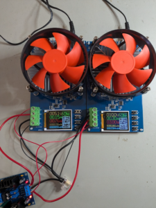
I also bought a couple of dummy loads and ran the power supply for a bit to increase my confidence that the voltage output was stable and that nothing else would go wrong. It seems to have worked reasonably well.
